Recommendations to keep in mind when designing in order to have successful products in Medium Detail Plastic (PLA).
![]()
![]()
![]()
![]()
Material Info
Plastic (PLA) is the most affordable way create prototypes. Models made out of PLA are constructed from thermoplastic. This material can be used to create all kind of prototypes from accessories to machinery parts or duplicates and many more.
The look and feel of the models can be described as hard and rougher compared to other materials.
The models are built layer by layer. A print head sucks plastic on one end, heats it until is melted and then pushes it through a fine nozzle on the other end. The print head moves and deposits the melted plastic on a platform layer by layer. The plastic immediately hardens again, creating one layer of your model each time. This process is called Fused Filament Fabrication (FFF) (you can find really nice tips about FFF here). Once the model is printed, we just take off its base on which was printed and your model is ready.
Disclaimer:
Bounding Box (size)
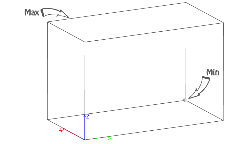
The bounding box represents the size we are able to print at once.
Min X + Y + Z ≥ 10mm
In order to be able to print your model, each of its pieces must be greater to those dimensions.
If the bounding box of your model is not bigger than our minimum, try scaling it up or making it thicker or enlarging some of its parts/features or any combination of the above.
Max 250x195x150mm
In order to be able to print your model, each of its pieces must fit within those dimensions.
If the bounding box of your model is bigger than our maximum, try scaling it down or removing unnecessary features/parts or cutting it to smaller parts or any combination of the above.
Wall thickness (minimum)
It represents the minimum wall thickness required in order to be able to produce your model, ship it and reach you unharmed. A wall could also be defined as the distance between two parts which form a closed and solid mesh.
Tip: The thicker the model, the more solid and safer to handle it gets. We recommend thicker walls for big and/or complex designs. The geometry of the model plays a crucial role on the solidity as well.
Supported (min 1.0mm at print size)
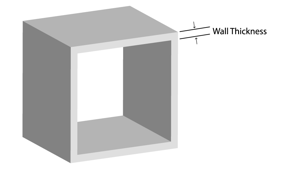
A wall is considered supported if it is connected to two or more walls on at least two of each sides.
If any supported walls are not thicker than the minimum required, try making them thicker, or adding supports or both.
Unsupported (min 1.0mm at print size)
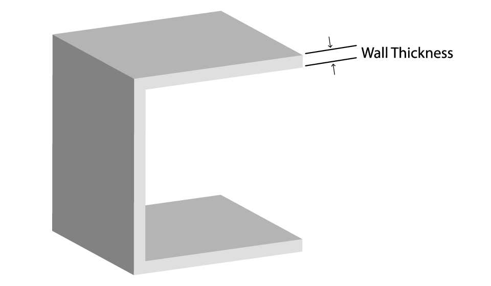
A wall is considered unsupported if it is connected to other walls on one side only.
If any unsupported walls are not thicker than the minimum required, try making them thicker or adding supports or both.
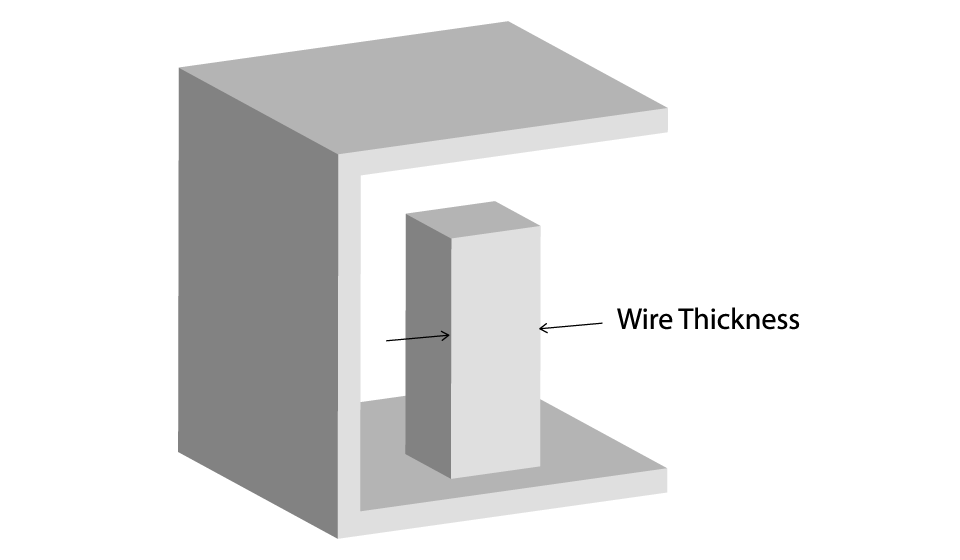
Wires
Wires are long and thin features of a model. As wire is considered a part whose length is two times greater than its width.
Tip: In general, wires follow the same rules as walls; nevertheless, due to their delicate nature you should be extra cautious when designing them.
Supported (min 1.0mm at print size)
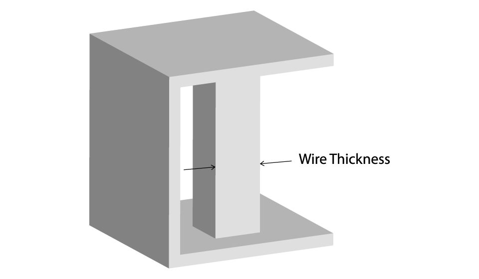
A wire is considered supported if it is connected to two or more walls on at least two of each sides.
If any supported wires are not thicker than the minimum required, try making them thicker, or adding supports or both.
Unsupported (min 1.0mm at print size)
A wire is considered unsupported if it is connected to other walls on one side only.
If any unsupported wires are not thicker than the minimum required, try making them thicker, or adding supports or both.
Details
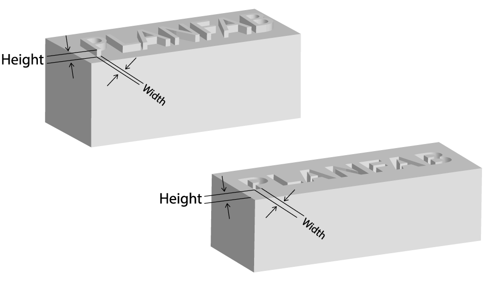
As details are considered all those features whose length is less than two times their width. Details could be either embossed or engraved on a surface.
Engraved
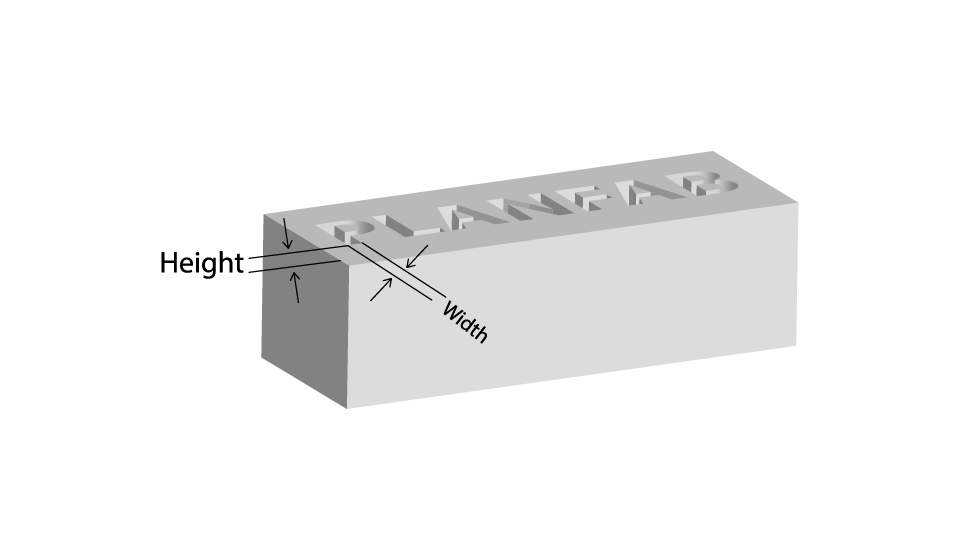
Minimum line thickness ≥ 2.0 mm
Minimum depth ≥ 1.0 mm
Embossed
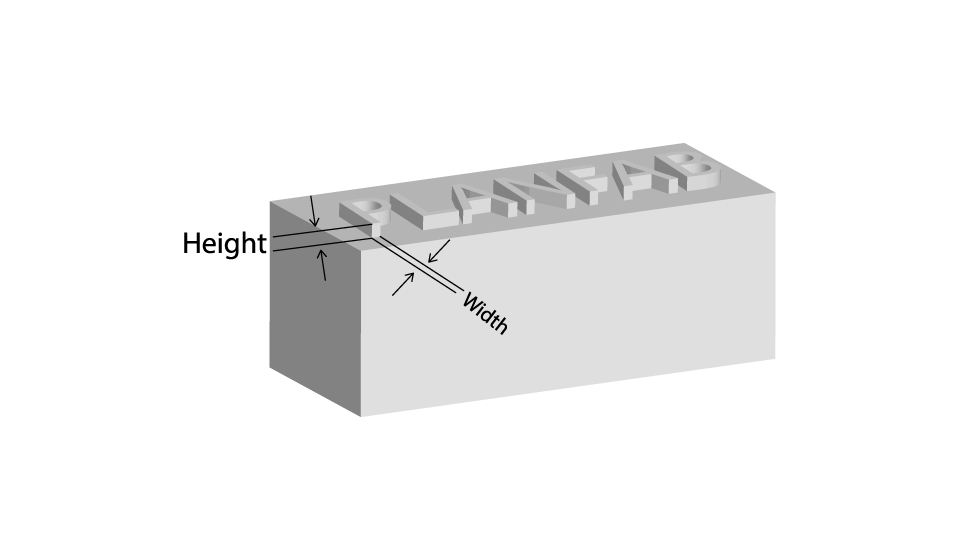
Minimum line thickness ≥ 1.5 mm
Minimum depth ≥ 1.0 mm
Make sure your detail’s length and width is greater than the minimum required, or else they won’t be clear and visible (the larger the detail, the more visible and clear it gets).
If any details on your model are not greater than the minimum required try making them bigger or removing them.
Clearance (1.0mm at print size)
Clearance is the distance between any two parts.
If your clearance is not over the minimum required, try making it greater or fuse the parts together if their independence is unnecessary.
Interlocking and enclosed parts
Yes. Plastic can produce interlocking and enclosed parts as long as the clearance is over the minimum and the model is properly designed for that purpose.
Multiple parts per model file
Yes. Multiple parts per model file can be processed and produced in Plastic.
Material Traits
Base
In order to build your model, the printer automatically creates a thin base on which to attach your model. At the end of the build, this base is separated from the model and is thrown away. Thus, have in mind that the bottom surface of your model will probably be rougher than the rest of the model.
Tip: You should take advantage of the automated base, clever design will get you great results. For example use it to keep interlocking parts still, such as the links on a chain.
Overhangs

Tip: There are ways to overcome the overhangs problems, such as creating arcs instead of corners or adding fillet for to prevent sagging. Another good way to avoid adding supports is to cut the model in parts, in order to achieve better print orientation, and glue the parts afterwards.
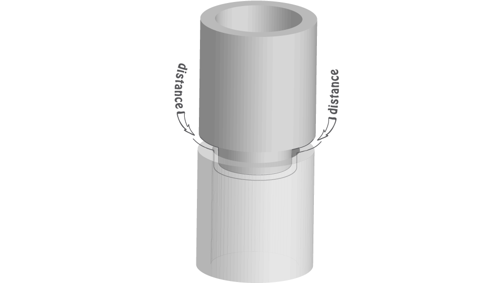
Assembly
Be careful when designing parts intended to be assembled, it is possible that the size of a model is not exactly the same size with your design. Thus, if your parts are not designed with some tolerance/distance, they might not fit together. Try to have at least 0.5mm distance between the parts at the assembly point. We generally really recommend, in cases you need a tight fit such as a screw in a hole, print the object and drill it afterwards.