Recommendations to keep in mind when designing in order to have successful products in Rubber.
![]()
![]()
![]()
![]()
Material Info
Rubber is an ideal way to create parts with elastomeric properties, bendable and compressible. Models made out with this 3d print technology are constructed from photo-reactive resin. This material can be used to create cushioning and dampening, functional prototypes, ergonomic prototypes such as handles and grips.
The look and feel of the models can be described as rubberlike. It looks similar to industrial rubber plastic. This material offers very high detail and is ideal for simulating soft-touch materials, adding soft overmolds to multi-material assembles, packaging, stamps and more.
The process uses visible spectrum light to cure the liquid resin one layer at a time. A resin bath sits above a laser which hits the surface of the resin at specific spots according to the geometry of the model. The resin immediately cures and turns into flexible plastic, thus, creating one layer of your model each time. This process is called Stereolithography (SLA). Once the model is printed, we take it off the machine platform and post process it with IPA and UV cure it.
Disclaimer:
Bounding Box (size)
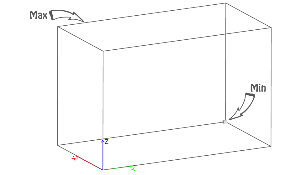
The bounding box represents the size we are able to print at once.
Min X + Y + Z ≥ 10mm
In order to be able to print your model, each of its pieces must be greater to those dimensions.
If the bounding box of your model is not bigger than our minimum, try scaling it up or making it thicker or enlarging some of its parts/features or any combination of the above.
Max 100x100x100mm
In order to be able to print your model, each of its pieces must fit within those dimensions.
If the bounding box of your model is bigger than our maximum, try scaling it down or removing unnecessary features/parts or cutting it to smaller parts or any combination of the above.
Wall thickness (minimum)
It represents the minimum wall thickness required in order to be able to produce your model, ship it and reach you unharmed. A wall could also be defined as the distance between two parts which form a closed and solid mesh.
Tip: The thicker the model, the more solid and safer to handle it gets. We recommend thicker walls for big and/or complex designs. The geometry of the model plays a crucial role on the solidity as well.
Supported (min 2.0mm at print size)
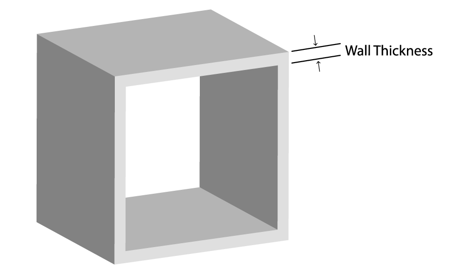
A wall is considered supported if it is connected to two or more walls on at least two of each sides.
If any supported walls are not thicker than the minimum required, try making them thicker, or adding supports or both.
Unsupported (min 3.0mm at print size)
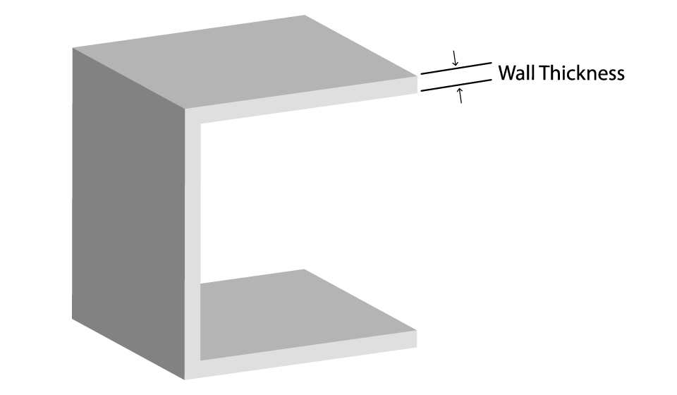
A wall is considered unsupported if it is connected to other walls on one side only.
If any unsupported walls are not thicker than the minimum required, try making them thicker or adding supports or both.
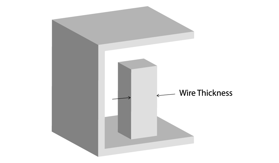
Wires
Wires are long and thin features of a model. As wire is considered a part whose length is two times greater than its width.
Tip: In general, wires follow the same rules as walls; nevertheless, due to their delicate nature you should be extra cautious when designing them.
Supported (min 0.9mm at print size)
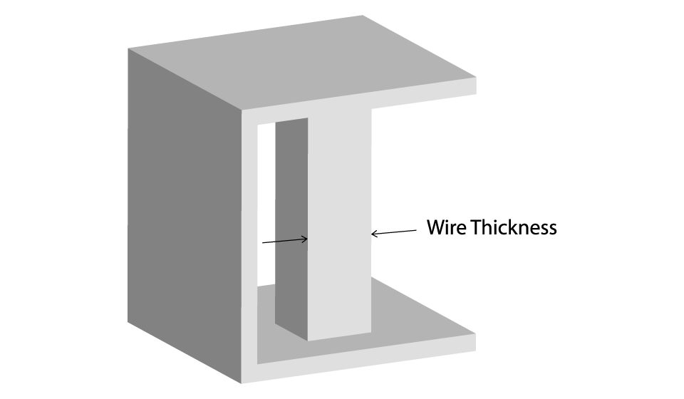
A wire is considered supported if it is connected to two or more walls on at least two of each sides.
If any supported wires are not thicker than the minimum required, try making them thicker, or adding supports or both.
Unsupported (min 2.0mm at print size)
A wire is considered unsupported if it is connected to other walls on one side only.
If any unsupported wires are not thicker than the minimum required, try making them thicker, or adding supports or both.
Details
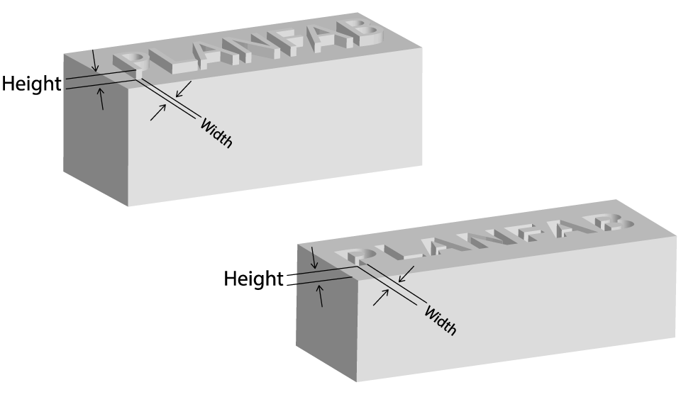
As details are considered all those features whose length is less than two times their width. Details could be either embossed or engraved on a surface.
Make sure your detail’s length and width is greater than the minimum required, or else they won’t be clear and visible (the larger the detail, the more visible and clear it gets).
If any details on your model are not greater than the minimum required try making them bigger or removing them.
Engraved
Minimum line thickness ≥ 0.4mm
Minimum depth ≥ 0.4mm
Embossed
Minimum line thickness ≥ 0.2mm
Minimum depth ≥ 0.2mm
Escape holes
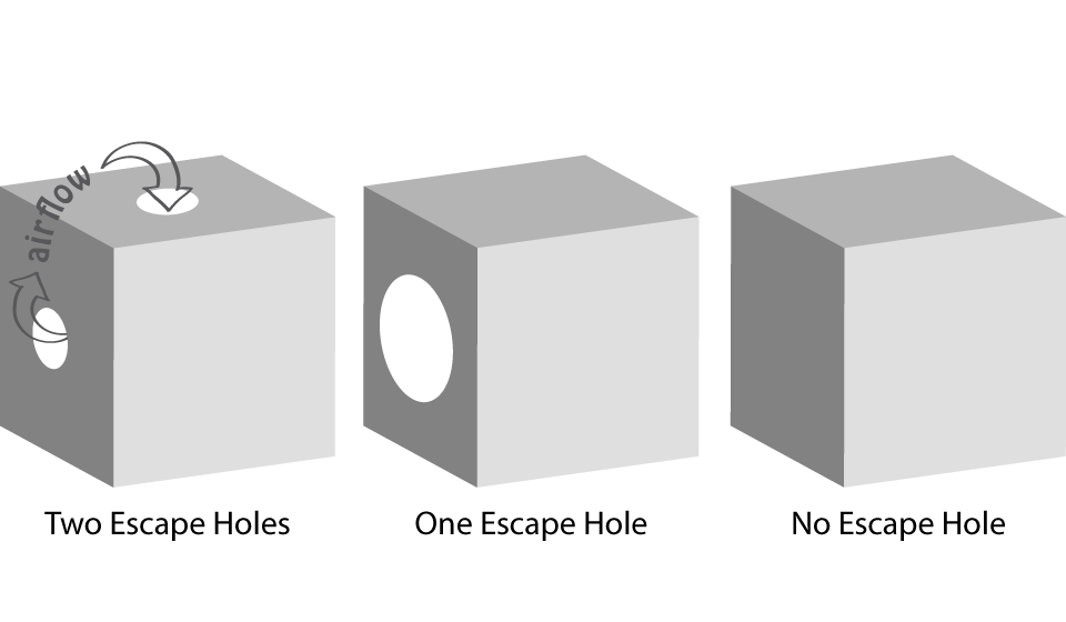
Drain holes are recommended for resin to escape in models that are a fully enclosed cavity (like a hollow sphere or hollow cylinder printed directly on the build platform). Without drain holes of at least 3.5 mm in diameter, the part may trap resin and lead to an explosion of the print.
If the model has complex geometry with many separate hollow cavities, make sure there is an escape route for every cavity.
If your escape holes are not sufficient and over the minimum requirements, try enlarging them or adding more or filling the hollow space or any combination of the above.
Clearance (0.5mm at print size)
Clearance is the distance between any two parts.
If your clearance is not over the minimum required, try making it greater or fuse the parts together if their independence is unnecessary.
Interlocking and enclosed parts
Yes. Rubber can produce interlocking and enclosed parts as long as the clearance is over the minimum.
Multiple parts per model file
Yes. Multiple parts per model file can be processed and produced in Rubber.
Material Traits
Rubber offers very high detail and is ideal for cushioning and dampening, for functional prototypes, for ergonomic prototyping such as handles and grips. This material is the best way to simulate soft-touch materials, for adding soft overmolds to multi-material assemblies, for packaging and stamps.
The material is heat resistant up to 120°C and long term exposure to UV light should be avoided. It is not suitable for simulating very high elongation materials (rubber band) or very fine features or thin walls.
| Rubber | |
| Elongation | 80% |
| Tensile Strength | 7.7 – 8.5 MPa |
| Hardness | 80 – 85A |
Design Tips: When setting up your part, make sure your model is in its final (rest) shape. For example, if you are printing a watchband, it should be it its circular form, not as a straight line. While designing your model, keep in mind that its flexibility will depend on its structure and thickness. A denser piece will be impact resistant but not very bendable.
Supports
Support structures are required to secure your model to the build platform, prevent warping and reinforce overhangs and other complex features. These support structures must be removed with a tool during post-processing. Surfaces which require support structures can be rough or show small imperfections due to the removal process. The production planners do their best to orient your models optimally to minimize the amount of support structures needed. It can be helpful to understand that the more overhangs and complex features in you model, the more support structures you will generally need.
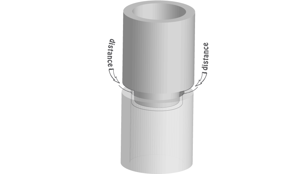
Assembly
Be careful when designing parts intended to be assembled, it is possible that the size of a model is not exactly the same size with your design. Thus, if your parts are not designed with some tolerance/distance, they might not fit together. Try to have at least 0.5mm distance between the parts at the assembly point. We generally recommend, in cases you need a tight fit such as a screw in a hole, print the object and drill it afterwards.